Yes another robot, and it's for entertainment only as always, but as with 98% of my robot builds there is some major or simple difference between them, this one is no different, it uses bump sensors (read micro switch) with an antennae glued to it. This robot has a few options that can be included. WARNING, only use 4 X 1.2 Volt rechargeable batteries, 1.5's will KILL the Arduino.
Now as always I stand on the shoulders of the many great women and men who went before me and in this case it's "J D Warren" of "Arduino Robotics" Book Fame, this one of his simpler projects but teaches you a lot about using servos and bump sensors. This is my version of that robot.
So, I decided to go with a Lady Bug theme and began with the planing stage as always and made up the template for the chassis, like my other builds I used 3mm thick MDF and 10mm dowel to hold the top to the lower chassis. I wanted to use what I had in stock to keep it as cheap as possible and went with Micro Servos, 9g versions, anyway more on this later.
Simple template made of plastic
The MDF Marked for cutting out
As I'm not the best at wood work I need to keep it as simple as possible, but you can let your imagination go wild and make what ever you like. I also cut out the motor brackets at the same time, I already have the template for them and I reuse it on most builds and it can be modified to take the large servo and micro servos as required. Don't forget to drill everything and get it ready for painting etc so you can do other parts of the build while the glue and paint dry.
The Main or Lower Chassis with Motor Mounts Glued in Place
Upper and Lower Chassis Components Drying
Okay, the chassis is on the way so I started on the Bump Sensors or Micro Switches, they have three terminals, a Common, Normally Open and Normally Closed, we need the Common and Normally Open terminals for this build but it could as easily be the other way around or both if you want, it's all in the Sketch/Code. So the "C" and "NO" terminals on the switch could have numbers or letters or both or nothing, lets test them with your multimeter to make sure, it's easy to tell the NC and NO as well as the C by using the beeper in the meter, with the switch in it's normal position the C and NO will make no sound and the C and NC will beep BUT in the switched position C and NO will beep and the C and NC terminal will go quiet, simple really.
These are the Rear 3 Micro switches made up
Black wires on the C or Common Terminal and Yellow on the Normally Open
Note the heat shrink, Black on Black and Yellow on Yellow
The 3 Black wires joined together and Heat Shrink applied
I like to use set colours for each job, Black is always the 0Volt or Earth, Red is always Positive or 5Volts or 3.3 Volts etc. Yellow is normally used as signal wires from sensors and to motors etc but I will also use green but they will be, front green and back yellow. My point is choose a colour scheme and stick to it, I have done this for 40+ years in the Auto Electrical game, I've also used the DIN Number system because we were the Bosch Warranty Agents for many years so it's in my genes.
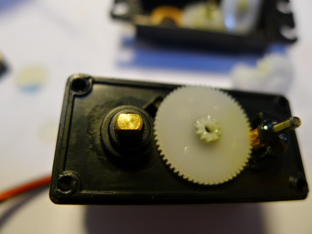
If you don't have continuous rotation servos you will need to modify them, I had normal micro servos so I had to do my mod, see Tubby Bot V1.0 or search the www, it's fiddly but not hard and the servo example in the Arduino IDE can be used to test them after the mod is done. Go and check the paint, if dry add more paint as desired, you choice really.
I used two larger Micro Switches for the front or antennae sensors
The terminals were bigger so I had to use a bit of red heat shrink, it's all I had in that size other than black. Now to make up the antennae, I used straws, the plastic ones you get for the kids parties, once I had tried it out on a test straw I made up the real ones, practise first as the hot glue and glue gun melt the straws quickly.
I put a small bend on the switch contact shaft
I guessed the angle for the switch contact shaft and cut the straw to a longer length than required, that way if it melted a bit I could trim them back to the size I wanted, worked that out after the 5th try, yes I'm quick.
Straw cut and fitted over the switch contact shaft
This is where it got tricky, you have to be quick with the hot glue and I filled the straw with the glue at both ends and let it cool and then trimmed to the correct length, as you will see it worked a treat, be careful that no glue gets on the under side of the shaft so it won't foul the operation. If you do let it cool totally and trim the excess with a good blade.
The finished antennae mounted on the chassis
I painted the straws and mounted the switch on each side of the "head" of the lady bug bot. Caster is up front this time as you can see and it works very well that way.
The switch was mounted with tie wire and hot glue put over the wire
I used tie wire to mount the switches and then used hot glue to cover the wire and add extra support for the switches, I did this front and rear, it made it very easy to mount the switches and glue them in place. I also use hot glue to hold the wires in place. apply the glue, wet your finger, (your choice as to how) and then press the glue down into shape, works very well, yes hot glue is my new best friend and yes I use a BOSCH glue gun, only the best.
Motor mounted in the motor bracket and wires hot glued down
Note that the motors are bolted on and I use flat washers to spread out the load, that way the bolts don't pull through the MDF, much stronger and looks good. I had to trim a flat on one side of the washer, I cut a small moon shaped piece off the washer so it missed the bit that sticks out the top of the servo. Easy with quality side cutters.

Motors, Bump Sensors, and Caster mounted
Bus Bar, Motor Harness and Lower Chassis sensor wiring
I like to make up a bus bar for the power and earths and I also use two pins with a joiner as the switch, cheap and easy to make up and handy for testing and programming etc. Battery holder I mounted on the top of the chassis and I used an Arduino Pro Mini so it is secured to the middle support with a cable tie, it's very cheap, has good memory for robotic purposes and I have a lot of them.
The rear sensor/micro switch mounted
The tie wire holding the switch on at the rear
The chassis ready for the Arduino and sketch/code
Once all the components were mounted and glued in place I loaded the sketch into the Arduino Pro Mini and did a test run, it needed lots of mods to suite the servos and I was using this computer, Banana Pi running Ubuntu with Arduino IDE but the IDE kept changing things, I didn't change the direction settings but it changed between two uploads along with other strange things so I swapped to the Windows Laptop made the alterations to suite my motors and it worked perfectly. It took three goes to get the motors perfect but they are now spot on and the grand kids love it, and that after all is what it's all about.
Battery holder on top cover over the caster for balance
The Motor Connector and Home made Plug, note the black negative terminal
The 3 rear sensors
The Arduino Pro Mini mounted to centre support
The motors, wiring and sensors
As I said the sketch/code was written by JD Warren of Arduino Robotics Book Fame I did change things a bit to match the servos and resistors that I used in the conversion so that the stop setting was in fact stop, one motor was 97 (not 90) and the other was 98, you will need to change the settings in the code to match your servos, this is not a sketch that will work with other motors and if you want that you will need to look elsewhere. Okay here it is with comments.
Sketch, Arduino_Bug_bot_code
// Bug-bot v1.2
// (2) Servo motors (modified for continuous rotation) with tank-steering setup (pins 9 and 10).
// (5) bump sensors total - 2 in front (pins 2 and 3) and 3 in rear (pins 14, 15, & 16).
// All sensors are normally HIGH (1) using arduino internal pull-up resistors.
// Sensors are brought LOW (0) by contacting the switch connected to GND.
// Either set of sensors can be used (front or back), by changing Mode Switch on pin 4.
// Pin 4 (HIGH or LOW) changes the bots default direction and sensors.
//
// include the Servo.h Arduino library
#include <Servo.h>
// create instances for each servo using the Servo.h library
// for more information, see: http://arduino.cc/en/Reference/Servo
Servo servo_L;
Servo servo_R;
////////////////////////// Variables used for testing (you can change these) /////////////////
// use to determine direction of bot and which sensors to use.
int mode_pin = 4; // connect the mode switch to digital pin 4
int antennae_L = 3; // connect left antennae sensor to digital pin 3
int antennae_R = 2; // connect right antennae sensor to digital pin 2
int bumper_R = 14; // connect right bump sensor to Analog pin 0, which is pin 14 when used as a digital pin
int bumper_C = 15; // connect center bump sensor to Analog pin 1 (digital pin 15)
int bumper_L = 16; // connect left bump sensor to Analog pin 2 (digital pin 16)
// Value to change servo stopping point pulse - use Code 7-2 to determine the specific pulse for each motor
int servo_R_stop = 90; // set the Neutral position for Right Servo - change as needed
int servo_L_stop = 90; // set the Neutral position for Left Servo - change as needed
// integers to use for updating Servo motors
// change these values to change the various motor actions
int stop_time = 1000; // stop for 1000 millliseconds = 1 second
int backup_time = 700; // backup for 700 milliseconds = .7 seconds
int turn_time = 300; // turn (either direction) for 300 milliseconds = .3 seconds
////////////////////////// End of variables used for testing ////////////////////////////////
// value names used to hold timing variables.
unsigned long timer_startTick;
// value names used to hold antennae states
int antennae_R_val;
int antennae_L_val;
// value names used to hold bumper states
int bumper_R_val;
int bumper_C_val;
int bumper_L_val;
// Set the forward and reverse speed values for the Right Servo based on the Neutral position
int servo_R_forward = servo_R_stop - 50;
int servo_R_reverse = servo_R_stop + 50;
// Set the forward and reverse speed values for the Left Servo based on the Neutral position
int servo_L_forward = servo_L_stop + 50;
int servo_L_reverse = servo_L_stop - 50;
// end of variables
// Begin Setup
void setup(){
Serial.begin(9600); // start Serial connection at 9600 bps
servo_L.attach(9); // attach servo_L to pin 9 using the Servo.h library
servo_R.attach(10); // attach servo_R to pin 10 using the Servo.h library
pinMode(mode_pin, INPUT); // declare input
digitalWrite(mode_pin, HIGH); // enable pull-up resistor
pinMode(antennae_R, INPUT); // declare input
digitalWrite(antennae_R, HIGH); // enable pull-up resistor
pinMode(antennae_L, INPUT); // declare input
digitalWrite(antennae_L, HIGH); // enable pull-up resistor
pinMode(bumper_R, INPUT); // declare input
digitalWrite(bumper_R, HIGH); // enable pull-up resistor
pinMode(bumper_C, INPUT); // declare input
digitalWrite(bumper_C, HIGH); // enable pull-up resistor
pinMode(bumper_L, INPUT); // declare input
digitalWrite(bumper_L, HIGH); // enable pull-up resistor
}
// End Setup
// Begin Loop
void loop(){
////////////////////////////////////////////////////////
// if the switch_pin is LOW, use the Antennae sensors
////////////////////////////////////////////////////////
if (digitalRead(mode_pin) == 0){
antennae_R_val = digitalRead(antennae_R); // read Right antennae
antennae_L_val = digitalRead(antennae_L); // read Left antennae
// Use Antennae sensors
// check to see if either antennae sensor is equal to GND (it is being touched).
if (antennae_R_val == 0 || antennae_L_val == 0){
// now check to see if only the Left antennae was touched
if (antennae_R_val == 0 && antennae_L_val == 1){
// if so, print the word "Left"
Serial.println("Left");
// reset timer
timer_startTick = millis();
// Stop motors
stop_motors();
// back up a bit
backup_motors();
// turn Right for a bit
turn_left();
}
// otherwise, if the Right sensor was touched and the Left was not,
else if (antennae_R_val == 1 && antennae_L_val == 0){
// print the word "Right"
Serial.println("Right");
// reset timer
timer_startTick = millis();
// Stop motors
stop_motors();
// back up a bit
backup_motors();
// turn Left for a bit
turn_right();
}
else {
// otherwise, both antennae sensors were touched
// print the word "Both"
Serial.println("Both");
// reset timer
timer_startTick = millis();
// Stop motors
stop_motors();
// back up a bit
backup_motors();
// turn either direction
turn_left();
}
}
else {
// otherwise no sensors were touched, so go Forward!
forward_motors();
}
// print the states of each antennae
Serial.print("Right sensor");
Serial.print(antennae_R_val);
Serial.print(" ");
Serial.print("Left sensor");
Serial.print(antennae_L_val);
Serial.println(" ");
// End Antennae sensors
}
///////////////////////////////////////////////////////////
// Else, if the switch_pin is HIGH, use the Bumper sensors
///////////////////////////////////////////////////////////
else{
// read the bumper sensors
bumper_R_val = digitalRead(bumper_R);
bumper_C_val = digitalRead(bumper_C);
bumper_L_val = digitalRead(bumper_L);
// Use Bumper sensors
// check to see if the right bumper was touched
if (bumper_R_val == 0){
// if so, print the word "Right"
Serial.println("Right");
// reset timer
timer_startTick = millis();
// Stop motors
stop_motors();
// back up a bit
ahead_motors();
// turn Left
turn_left();
}
// check to see if the left bumper was touched
else if (bumper_L_val == 0){
// if so, print the word "Left"
Serial.println("Left");
// reset timer
timer_startTick = millis();
// Stop motors
stop_motors();
// back up a bit
ahead_motors();
// turn Right
turn_right();
}
// check to see if the center bumper was touched
else if (bumper_C_val == 0){
// if so, print the word "Center"
Serial.println("Center");
// reset timer
timer_startTick = millis();
// Stop motors
stop_motors();
// back up a bit
ahead_motors();
// turn Left
turn_left();
}
else{
// otherwise no sensors were touched, so go Forward (which is actually Reverse when the direction is switched)!
reverse_motors();
}
// print the states of each bumper
Serial.print("Right Bumper: ");
Serial.print(bumper_R_val);
Serial.print(" ");
Serial.print("Left Bumper: ");
Serial.print(bumper_R_val);
Serial.print(" ");
Serial.print("Center Bumper: ");
Serial.print(bumper_L_val);
Serial.println(" ");
}
// End Bumper sensors
}
///////////////////// End Loop /////////////////////
// Beginning motor control functions
void stop_motors(){
// stop motors for the amount of time defined in the "stop_time" variable
while(millis() < timer_startTick + stop_time){
servo_L.write(servo_L_stop);
servo_R.write(servo_R_stop);
}
timer_startTick = millis(); // reset timer variable
}
void backup_motors(){
// backup for the amount of time defined in the "backup_time" variable
while(millis() < timer_startTick + backup_time){
servo_L.write(servo_L_reverse);
servo_R.write(servo_R_reverse);
}
timer_startTick = millis(); // reset timer variable
}
void ahead_motors(){
// go forward for the amount of time defined in the "backup_time" variable
while(millis() < timer_startTick + backup_time){
servo_L.write(servo_L_forward);
servo_R.write(servo_R_forward);
}
timer_startTick = millis(); // reset timer variable
}
void turn_right(){
// turn right for the amount of time defined in the "turn_time" variable
while(millis() < timer_startTick + turn_time){
servo_L.write(servo_L_forward);
servo_R.write(servo_R_reverse);
}
}
void turn_left(){
// turn left for the amount of time defined in the "turn_time" variable
while(millis() < timer_startTick + turn_time){
servo_L.write(servo_L_reverse);
servo_R.write(servo_R_forward);
}
}
void reverse_motors(){
// go reverse indefinitely
servo_L.write(servo_L_reverse);
servo_R.write(servo_R_reverse);
}
void forward_motors(){
// go forward indefinitely
servo_L.write(servo_L_forward);
servo_R.write(servo_R_forward);
}
// End motor control functions
// End Code
The major area to be changed is the "int servo_R_stop = 90" line and or
"int servo_L_stop = 90", if you have wired everything else as per the sketch, and don't forget the switch for the mode of operation, D4 earthed "0" will have it moving toward the antennae up front and open "1" with the internal pull up resistor turned on will have it operate in reverse and it will rely on the 3 rear sensors. If you want to use this feature you will need to fit a switch to D4 and to 0 Volts, I'm not using the feature at the moment but will when I sort out rear sensor plates that fit on to the rear micro switches. So I have the D4 terminal earthed. You can drop me a line at terrencej.banana.pi@gmail.com if you like and play nice please or I won't reply. Once again this will NOT work with normal DC permanent magnet motors so please don't ask, I won't answer you.
Okay or OK, a very short video to show that it does work in the forward direction, it also works the other way but I didn't video it, Cheers and enjoy.
Smile and be nice to one another, it really does make your day better, TJ. Remember, it's all in the sketch.