In my posts I have made reference to Continuous Rotation Servos and indicated that you can find instructions on the Internet or included it in a post with other builds, well I have decided to show how I did it when I purchased some new Futaba S3003 Standard Servos and needed to modify them so I took a series of images so I can demo that process. These servos cost me $11.00 on eBay with free postage from inside Australia so they were cheap enough given it was an Aussie purchase. Remember this is for entertainment only but it worked perfectly for me and should for you.
The Servo and Tools Required for the Conversion
A Multimeter is also a must have
In image one you can see the tools and parts required for the conversion, the only electrical components are two 2K7 Ohm through hole resistors and a standard servo or two and some silicone lubricant. Not in the image is my Soldering Iron and solder. By "standard servo" I mean the ones that are normally used for RC Planes and Cars, they only turn through 180 degrees or so and when finished they will be able to turn continuously when the correct signal is applied to them. We do this because they are by far the cheapest servos available and they make fantastic high torque fast motors, well fast enough for robotics use anyway. The only special bit of kit that you will need is a good multimeter as in image two, I recommend you invest in a good quality meter, that way it will last you for many years and give accurate readings over it's life time.
My Servo has Four Screws
Okay lets get to it, first look for the screws that hold the servo together, see above, and get the screwdriver to match the screws, pick the correct one so you don't damage the heads of the screws, it easy to do so be careful. If the servo only has two screws undo one then the other but if it has four then I recommend you undo one then undo the diagonally opposite screw and so on, good practise and helps prevent warping the cover, yes I know over done but it's still good practise.
Inside the Servo with End Cap Removed
Screws out, now carefully remove the end cap, take note of the layout and if needed take a photograph so you can put it all back the same way. On my servo I wasn't able to lift the PCB (Printed Circuit Board) out but you may be able to do so with yours, carefully test it to see if it can come out, if it has wires connecting the position sensing potentiometer (Pot) to the PCB it should come out. Take careful note of how the wires are connected to the PCB, that is where the wiper of the pot is connected and the two outer terminals of the pot as well, draw it so you don't get it wrong, it's very important. Also be careful not to brake the other wires off. Lets take a moment and test the potentiometer so we know which one is the wiper, now 99% of the time the middle pin is the wiper but you never know with cheap servos. First test the two outer pins with the meter set to Ohms, the omega symbol on the dial, you should get 5K0 Ohms, remember that, it's important. Now test from one outer pin and the middle pin, it should read somewhere between 0 and 5K0 Ohms, now turn the pot shaft and the resistance should change as you turn the shaft, that is the wiper terminal of the pot and it must go to the centre of the voltage divider network that we make with the two 2K7 Ohm resistors. The 5,000 ohms was important because we need to use two resistors in series that total 5,000 ohms, we can use 2K2 or 2K7, I like to use 2,700 ohms (2K7 Ohms), its gives 5,400 ohms which to me is better than 4,400 ohms, yes i know 6 of one and half a dozen of the other, I'm fussy and I like to be safe, it's up to you really. Also use 1% 0.25W resistors, that way the voltage divider is exactly half the supply voltage and that signals the 90 degree or centre position of the servo. That way you can set a Stop position in the sketch for your robot by requesting the 90 degree position, any thing less or more will make the motor rotate one way or the other and it keeps going because the position feedback never changes, you can also change the speed but that's out of the scope of this story and I need to study it more to be sure. Anyway back to the job.

The Gearbox Housing Comes OFF as well.
The Gearbox Cover and Gears Removed
My servo had to be totally dismantled at this stage, you will also need to do this, so carefully remove the gearbox cover and take special note of how it all goes together, take a photograph so you get it right or it won't work. You will see why you need to do this a bit later. So, with mine apart I had to remove the pot and PCB together, you will see that the output shaft is connected to the position sensing potentiometer (Pot), the bigger brass looking shaft in the gearbox, you need to push this shaft out of the motor housing without breaking anything.
The Pot shaft is on the Left, the big one
Apply pressure to the Shaft to pop it out
Put the pot shaft against your bench, see image above, and firmly push it out of the motor housing, it is held in by a plastic clip so it will need a bit of pushing but be careful not to break anything.
The PCB and Pot came out Together in my Servo
Unsolder the Pot Pins from the PCB
You need to cut the wires AT THE POT if yours is connected by wires or like mine you will need to unsolder the pins at the PCB, use a solder sucker and be careful not to unsolder the surface mounted components that are also connected to the pins, take you time and be very careful because they are hard to put back on, Clean out the holes so we can solder the two 2K7 Ohm Through Hole Resistors to the PCB or if your Pot had Wires you need to connect the resistors to the wires that you cut off at the pot.
Twist the Resistor Leads Together Like This
Now Bent the Other Two Like This
Now twist two of the resistor leads together as in the first image above and then bend the other two as in the second image above. So if your servo had wires you will need to cut some heat shrink, three bits about 10mm long and slide them over the three cut wires, put the wire that went to the wiper onto the twisted pair of leads from the resistor and solder it, now slide the heat shrink up and heat it so it insulates the connection and leads, solder the other bent leads to the other two wires and solder them and insulate them with the heat shrink. It doesn't matter which way they go because we are making a voltage divider network and the wiper is the critical connection and goes to the middle of the voltage divider, that is the twisted pair of leads. In my servo it was a bit easier to do, see image below.
The Resistors Mount on the PCB as above
In my servo the resistors mount on the underside of the PCB and solder to the PCB, the important one is the twisted pair again and they must go where the wiper of the pot was, once again making a voltage divider network and the middle goes to the wiper connection. Take care not to damage the PCB and or the surface mount components on the PCB.
Mount a torch in your little vise or bench like this
Now Inspect the PCB for Bridges or Damage as shown above
Mount a torch as in the first image above and position the finished PCB as in image two above so you can see the light through the PCB and inspect it for solder bridges or damage, this makes it very easy to see any faults. no need to use heat shrink on this pair of resistors. Now put it all into the motor body making sure nothing can short out and in the same position as it was originally, look at the photographs to make sure it's all as it was.
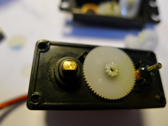
We Need to Modify the Output Shaft
We now need to modify the output shaft so it can rotate continuously, the stopper on the shaft that you can see on the right in the image above must be carefully removed. I use a very small hobby saw and cut it off at the top of the gear teeth, once removed I use a diamond file to make it flush with the teeth and flush with the shaft at the other end, be careful not to damage the teeth or the shaft and give it a good clean to remove the bits that you cut and file off.
Now put a bit of extra silicone lubricant on the gears and put the gears back together, look at the photograph to make sure they are as they should be and put a bit more silicone lubricant on the gears and output shaft, especially where the bush is for the output shaft itself.
Gearbox Back Together and Lubricated
Note the extra Lubricant at the Output Shaft Itself
Now put both covers back on making sure that all gears and wiring are in their original positions and nothing gets caught up or damaged, put the screws back in and torque them so that you do diagonally opposites as you go. Once together you need to test them.
The Test Setup on the Bench
Set up a test using an Arduino UNO or what ever you have and the Arduino IDE and the example sketches that come with the IDE, the servo should rotate one way continuously and then the other and not make strange noises and run freely both ways. The wiring for the servo is Red = 5V "+" and it is always the centre pin in the 3 pin plug, Black or Brown = 0V "-" and then Orange, White or Yellow = Signal from the Arduino or tester, now program the arduino with a sketch for servos and make sure the servo works as intended, remember the servos work on 5Volts and the arduino can power them but I recommend to power them from the battery or power supply directly, easier on the arduino regulator, just remember to join all 0Volt or earths together. Cheers, and have fun, Terry.