Friday, 26 June 2015

RTL.SDR 30MHz to 3GHZ Ultra-Wideband Home Made BI-CONICAL ANTENNA

Yes I did write 30MHz to 3GHz and yes I have built it and tested it and it surprised me but to test it across the full 30 to 3 really is out of my league but it made a huge difference to the number and strength of signals that I was receiving. This is my version of a design I found on YouTube at;
https://www.youtube.com/watch?v=xhW4QQruBTo
I didn't have the money to get the aluminium sheet at $105.00AUD each (at Masters) and I needed two so I came up with the next best thing, a roll of Hardaz Vermin Wire Mesh 6.5X6.5mm, 15cmx10M roll for about $20.00AUD. It wasn't wide enough so I modified it by soldering two lengths together and it almost came out at the correct size, so close it didn't matter to me anyway. Now to make a CONE is a bit tricky and it took me a few goes with big sheets of paper first but it worked okay in the end, mind you it isn't pretty but it tests perfectly electrically and works very well.

                   It looks a bit like an hourglass - Bi-Conical Antenna V1


                             The centre spacer is a plumbing pipe joiner

The top and bottom formers are 10mm MDF and the three supports are good quality dowel, I also cut out some curved MDF to hold the wire in the centre and as circular as possible, you can just see one of them to the right of the centre dowel on the bottom former. All the dimensions are in the video for the wire and you will need to design your own support frame. As I said it isn't perfect, even a bit wonky but it works very well. The RTL.SDR comes with a Small antenna and simply didn't work at all in my location so I made up a 2M coaxial co liner dipole with three elements and it works fantastically on the amateur band but not much good above and below that. The bi-conical was picking up hundreds of automotive RF remote door lock transmitters on my first try, amazing to listen to, yes I'm nuts I know, also I was listening to aircraft coming and going from Sydney airport and I live in Bathurst, on a big hill and I look towards Sydney from my yard and I couldn't do that on the original antenna or the coaxial antenna so if you want to build a cheap antenna that works amazingly this is the one for you. By the way get it up as high as possible and it will blow you away I'm sure, it did me.
PS. I forgot to mention that I got the RTL.SDR so I could receive and play with the Cubesat, Amsat and othersat's out there so I will be building a yargi or two to get good signals for them and most of the sensors have arrived for the Arduino home based sat so more on that later as well.

Saturday, 30 May 2015

ArduSat; Arduino in Space.

Well I don't know about you but I love Electronics, Arduino, TI LaunchPad, Freescale FRDM Platform and every other development board out there and I get up to 10 e-mails a day from all the popular electronic stores and the like and I got one the other day and I was instantly hooked. It was about Arduinos and Space, NASA's Curiosity Rover team member Luke Dubord and our very own Jonathan Oxer from "Freetronics", it was Freetronics that sent the e-mail and I use a bit of his gear in my robotics development etc. All of my robots use the Arduino Platform, I have a few genuine boards and a lot of clones but it is all Arduino based. I have ordered all of the components and I will be playing with them in a very low orbit, ie my computer room, but you must check it out,
https://www.ardusat.com and also check out;
 www.youtube.com/watch?v=0GHMTXiDqoA
and another one to look at is;
www.edn.com/electronics-blogs/esc/4439386/13-engineering-truths-proved-by-NASA-s-Curiosity-Rover
This should be the link to the e-mail online;
http://us6.campaign-archive2.com/?u=6c6eae339297e03e05631429d&id=6fe06ca8b0&e=106891729c
just copy and paste it into your browser, it worked perfectly for me.

The sensors that you will need include a Luminosity Sensor, Temperature Sensor, Accelerometer, Gyroscope, Magnetometer, Ultraviolet Light Sensor and Infrared Thermopile but one of them is a 10DOF IMU Sensor Module that has a number of the sensors built into it, I got mine from Core Electronics in Australia on eBay for $24.00AUD but they are available on eBay from China for a lot less, I like to shop at home as much as I can.

The Ardusat site has most of the information required and links to github for the Arduino libraries etc needed for all of the sensors and example sketches to test them and away you go, some of the best education information that I have found on the Internet from anywhere in the world about electronics and Arduino, it's a must.

Cheers, Terry.

Monday, 18 May 2015

TJ's Rover 5 (Product Report and Build)

The Rover 5 from HobbyKing.com

This is for entertainment only but it worked perfectly for me.

I have wanted a rolling robot but "Track Driven" for some time and when I saw the Rover 5 advertised on HobbyKing.com I just had to have one. The pricing varied a bit depending on whether you wanted Two Motors, Four Motors and Speed Encoders. I don't have the need for speed encoders and the cost for two extra motors was a bit out of my reach so I settled on the basic two motor no speed encoder version. I purchased it when I purchased the Line Tracing Robot so they shared the cost of the freight but it still cost a lot but it did arrive very quickly from China so it was worth it. Total Cost was $39.44 delivered to my door, not bad really.

                    This is what you get in the kit plus a 6 Cell Battery Holder


                            My version has Two Motors and No Encoders

You can dismantle the motor and drive wheels front and rear and adjust the ground clearance as well as tension the rubber track if required. I left mine as it came in the box. I had to consider what style of control I was going to use and whether I wanted to add to its operational capabilities later or not. I chose a simple set up first and decided to use Infrared sensor for obstacle avoidance, a servo to point the IR sensor across the front of the robot and I had a few Arduino Adafruit Motor Shields made by DK Electronics as well as a DCcduino Arduino Uno in my parts bin so that dictated how it was to be controlled.

                                      This is the Infrared Sensor I used

                               I put some Heat Shrink on it for Protection

I had some IR sensors that I purchased a few months ago and I got then for $1.00AUD. I protected it with some heat shrink and glued a servo horn on the underside and left the adjustment trim pot uncovered so I could adjust the sensitivity of the sensor later on in the build. I will use four more later on when I design and build a robot arm for the robot, that will give it finer control over it's position.

                           The Servo Arm or Horn glued to the underside

I used a standard size Servo, one with plastic gears because it isn't doing heavy work and they were very cheap, $13.00AUD from Micro Engines in Australia, supporting the Local Bloke.

                                            The Servo that I used

                                      IR Sensor mounted on the servo

The Adafruit Motor Control Shield is one of the simplest motor control shields to use, it has a huge number of sketches already written by the Arduino Family and as always I Stand on the Shoulders of the great Women and Men that went before me and use the sketches that are out there for most of my builds and this one is no different. It was George Frick that did the original work on the sketch that I am using.

                                          The Adafruit Motor Controller

                                    The Arduino Uno Clone that I used

The Arduino Uno Clone that I used can be purchased from China for about $5.50AUD at the moment, it doesn't use the DIP chip so if it fails you have to replace the unit as a whole but they are very cheap anyway. I do have a genuine Arduino Uno that I use for programing the chips that I use in homemade builds and prototyping work.

                        The Beauty of the Adafruit shield and Arduino Uno

As you can see from the above image the beauty of the Adafruit Shield and the Arduino Uno is they clip together and occupy the same footprint in the build as well as having two servo outputs and the six A0 to A5 inputs, six 5V+ and 0V- pins all close together for easy wiring. I think that this is V2 but it is still available in clone forms for about $5.00AUD from China so they are very cheap as well.
As I mentioned you get a six cell battery holder in the Kit and I wired a switch to the earth or 0V line as well as a 2.1mm plug for the arduino power socket and two power wires to connect the 9V to the Motor Control Shield for maximum power for the motors. The combination or parts that I used makes it very easy to power and wire up the robot and lends itself beautifully to modifications and upgrades later on which is what I want to do in time with this robot base.

                                   The Six Cell Battery Holder in the Kit


              The Switch, 2.1mm Plug and Power Wires for the Motor shield

I have cut out a bit of 3mm MDF for the Rover 5 chassis that fits over the opening on the top of the robot so I can mount the components on the robot. I have cut out an opening for the servo motor to mount in and some holes for screws and wiring to go through so it is all safe and secure for operation. I mounted the components onto the MDF and had to put some spacers or standoffs under the mounting brackets for the servo as well as long screws, nuts and washers to get the clearance required for the batteries and wiring etc in the chassis. As it happens it worked out fine and stage one works well given how simple it really is.

                                      Rover 5 Looking at the Front


                                              Rover 5 Side View

The wiring is simple, the motor shield does most of the connections required for the Arduino Uno and then all you need to connect is the servo to the Servo 1 connection on the shield and the 5V+, 0V- and the output from the IR Sensor to power supply terminals on the shield and to A5 on the analog pins on the shield as well as the motor connections. You can have as many as four DC Motors controlled via this shield and in this case M1 and M2 are used and if the motors are going the wrong way just swap the motor wires around, M1 is the right hand motor and M2 is the left so it really is very simple.

           The ON/OFF Switch is mounted between the servo and arduino


                                    The Servo has just enough clearance

You will need to adjust the IR sensor to get the best result but other than that the Sketch works perfectly on my Arduino Clone and adafruit motor shield, This is the code that I used, enjoy.


/*
 * George Frick (george.frick@gmail.com)
 * Jan/Feb 2010.
 * Arduino Robot 2 - Wandering Tank
 * This robot will wander around, scanning with a very short range forward IR.
 * When an object is detected, the robot will turn based on the position of the IR sensor
 * during the detection. The robot will move backwards, then turn away from the detected object
 * and continue. The robot runs continuously.
 */
#include <AFMotor.h>
#include <Servo.h>

// Two motors, a servo, and an IR sensor.
AF_DCMotor motor1(1, MOTOR12_64KHZ); // create motor #1, 64KHz pwm
AF_DCMotor motor2(2, MOTOR12_64KHZ); // create motor #2, 64KHz pwm
Servo sensorServo;
const int irPin = 19; // pin 5 as digital is pin 19

// Timing. I don't like using delay.
unsigned long tCnt = 0;
unsigned long tStart = 0;
unsigned long tDelta = 0;
unsigned long tTurn = 0;

int state;               // Current Robot State
int lastState;           // Previous Robot State
int servoPos;            // Position to send servo
int servoDirection;      // Direction servo is turning
int lastDetectionAngle;  // Position of servo at last IR detect.

// Constants for state of tank tracks.
const int STATE_FORWARD = 1;
const int STATE_TURN_RIGHT = 2;
const int STATE_BACKWARD = 3;
const int STATE_TURN_LEFT = 4;

// Constants for Servo.
const int DIR_LEFT = 0;
const int DIR_RIGHT = 1;
const int MIN_DEGREE = 40;
const int MAX_DEGREE = 140;

/*
 * Initializes everything. Is run once.
 */
void setup() {
  Serial.begin(9600);           // set up Serial library at 9600 bps
  sensorServo.attach(10);  // attaches the servo on pin 10
  pinMode(irPin, INPUT);
  motor1.setSpeed(255);     // set the speed to 200/255
  motor2.setSpeed(255);     // set the speed to 200/255
  tStart = millis();
  lastState = state = STATE_FORWARD;
  servoPos = 90;
  servoDirection = DIR_RIGHT;
  sensorServo.write(servoPos);
  //state = 0; // Uncomment to have robot not move tank tracks.
}

/*
 * Runs continuously.
 * 1. Update Servo.
 * 2. Check IR sensor.
 * 3. Move Robot
 */
void loop() {
  tDelta = millis() - tStart;
  tCnt += tDelta;
  tStart += tDelta;

  // Tell the servo to move 2 degrees every 25 ticks.
  if( tCnt > 25 ) {
    tCnt = 0;
    if( servoDirection == DIR_LEFT ) {
      servoPos -= 2;
    } else if( servoDirection == DIR_RIGHT) {
      servoPos += 2;
    }

    // Servo position will be beyond desired angles, turn around.
    if( servoPos >= MAX_DEGREE ) {
      servoDirection = DIR_LEFT;
    } else if( servoPos <= MIN_DEGREE ) {
      servoDirection = DIR_RIGHT;
    }
    sensorServo.write(servoPos);
  }

  // Allows disabling of tracks by setting state to 0.
  if(state == 0) {
    moveRobot();
    return;
  }

  // Double read the pin, @see forums.adafruit.com
  digitalRead(irPin);
  delay(5);
  if( digitalRead(irPin) == 0 ) {
    lastDetectionAngle = servoPos;
    state = STATE_BACKWARD;
  } else {
    if( state == STATE_BACKWARD ) {
      if( lastDetectionAngle > 105 ) { // right
        state = STATE_TURN_LEFT;
        tTurn = 1000; // turn for ~1 seconds
      } else if( lastDetectionAngle < 75 ) { // left
        state = STATE_TURN_RIGHT;
        tTurn = 1000; // turn for ~1 seconds
      } else { // center
        state = STATE_TURN_RIGHT; // for now, turn right by default.
        tTurn = 1500; // turn for ~1 seconds
      }
    } else if ( state == STATE_TURN_RIGHT || state == STATE_TURN_LEFT ) {
      tTurn -= tDelta;
      if( tTurn <= 10 ) {
        state = STATE_FORWARD;
      }
    } else {
      state = STATE_FORWARD;
    }
  }

  moveRobot();
}

/*
 * Uses the state of the robot to move tank treads accordingly
 */
void moveRobot() {

  // The motors seemed to respond better if they receive a stop before a switch in direction.
  if( state != lastState ) {
    motor1.run(RELEASE);      // stopped
    motor2.run(RELEASE);      // stopped
  }

  switch( state ) {
    default:
      return; // helps test, state 0 = dont move.
    case STATE_FORWARD: {
      motor1.run(FORWARD);      // turn it on going forward
      motor2.run(FORWARD);      // turn it on going forward
      break;
    }
    case STATE_BACKWARD: {
      motor1.run(BACKWARD);      // turn it on going forward
      motor2.run(BACKWARD);      // turn it on going forward
      break;
    }
    case STATE_TURN_RIGHT: {
      motor1.run(FORWARD);      // turn it on going forward
      motor2.run(BACKWARD);      // turn it on going forward
      break;
    }
    case STATE_TURN_LEFT: {
      motor1.run(BACKWARD);      // turn it on going forward
      motor2.run(FORWARD);      // turn it on going forward
      break;
    }
  }

  lastState = state;
}

/* EOF */

My thoughts on the product or if I had to give it a score out of 10 I would give it an eight, 8/10, it lost two points because the battery holder had an opencircuit on the 0V- line at the soldered joint in the holder itself. Other than that it has huge amounts of power and remember I have the two motor version so four motors must be twice as powerful and ease of mating your build to the chassis is excellent with four screw mounting points that you can tap out for 3mm machine thread screws, that is what I did on mine and it worked perfectly. If you are looking for a tank style chassis motor setup this is one that I would highly recommend.
If you copy and paste the above code into your Arduino IDE it should work perfectly when used with the components that I used so have fun.

This is a very short video of it in operation;


Tuesday, 12 May 2015

DC Bot, Product Test, HG7881CP Motor Controller

As always this is for entertainment purposes only but worked perfectly for me when used with the components listed, it won't work with other motor controllers so please don't ask, but have fun with it.

I have had some very small DC motor controllers for some time now and didn't feel confident enough to write my own sketch for them and I couldn't find one that suited the unit so they sat in my parts box not being used. So I have been modifying sketches for a while now and finally I decided to write a sketch for the motor controller, it's the LC Technology HG7881CP Motor Controller, it's a full H Bridge and can carry 800mA total as well as 12V operation if you wish, it will run on 2.5V to 12V. The cost for this controller on eBay is about $2.00 to $5.00 delivered so it's as cheap as chips and will handle those cheap Arduino Robot Kits that use the little yellow geared motors. My tests showed that this motor only drew about 200mA to 600mA at stall on 5V so they should be perfect and that is what I used for this build except I purchased the robot kit from Jaycar Australia mainly because of the wheels that were in the kit so it cost me a lot more than you can buy them from China but I had to support the local bloke at least once, but at $54.00AUD it will be the last time, I'll make my own in future.


                                  This is the Schematic for the Controller

                               The HG7881CP H Bridge Motor Controller

The other components were a HC-SR04 Ultrasonic Sensor, an Arduino Pro Mini Clone, some 3mm MDF, 10mm dowel, assorted small washers, screws and plastic components for insulation and mounting the components not to mention wire, terminals and rechargeable batteries. As I mentioned I purchased the robot kit from Jaycar which came with a switch, two yellow geared motors, caster wheel, plastic chassis and nuts, screws standoffs and encoder wheels which I didn't use.

So, the first thing I did was research the HG7881CP controller and get all the information I could on it, the best bit of information was a Truth table and a list of terminal IDs.
  1. B - IA; Motor B input A, (IA)
  2. B - IB; Motor B input B, (IB)
  3. GND; Ground, 0 Volts
  4. VCC; Supply + Voltage, 2.5 to 12 Volts
  5. A - IA; Motor A input A, (IA)
  6. A - IB; Motor A input B, (IB)
Truth Table:   IA - IB      Motor State
                        L - L      |       OFF
                        H - L     |    Forward
                        L - H     |    Reverse
                        H - H    |        OFF

The other bit of information was that the IA connections should be PWM signals and that the IB connections should be Digital High or Low for Direction Control. With this information I stood on the shoulders of the great women and men that went before me and imported some code that I have used many times for control of the ultrasonic sensor, and went with  NewPing.h and using the truth table I wrote the void moveBackward, move Forward, moveRight and moveLeft as well as moveStop sketch instructions and rats nested the circuit on the bench and loaded the sketch into the Arduino Pro Mini clone and tested the operation of all components and to my surprise it worked perfectly first try, but needed some fine tuning once the robot was built.

                                    The components on the Bread-Board


Okay, the build started with me cutting out the top deck of the robot out of 3mm MDF, I like the robots I build to have a lower and upper deck and I also like to paint the bot to liven it up a bit, which is just what I did for this build. While the Paint was drying I started on the other components.

The HC-SR04 Ultrasonic Sensor needed a bracket and as always I make mine out of some universal PCB and solder the bits together to make up the bracket, see images below.

                                    The PCB cut to form the bracket

                The two parts soldered together so they are at 90 degrees

I then make up some wire supports to hold the Ultrasonic Sensor to the bracket and solder it all together so it becomes a sturdy mounting support,see images below.

                             The mounting wires soldered to the HC-SR04

                                     The finished bracket and HC-SR04

Sensor ready for mounting it now came time to mount the Arduino Pro Mini Clone to some PCB and fit some connection pins on the PCB as well so it can all be wired together and mounted on the robot chassis, doing it this way makes it very easy to mount and wire up. Now fit a 0.1 uF cap across the motor supply terminals to filter the brush noise from the motor to help protect the motor controller, I always do this. The paint was now dry and so I was able to start mounting the components onto the lower chassis, see images below.

                  The Motor with Mounting Bracket and Filter Capacitor


                A shape proof washer is always used on the motor bracket

I like to use a shake proof or star washer on the motor brackets and flat washers under the head of the screws to spread out the load of the screw over a larger area, helps prevent breakage especially on the plastic chassis.

           Flat washers under the head of the mounting screws for the motors


                 Both motors mounted to the underside of the lower chassis

                     Mounting screws and standoffs on the battery holder

I use plastic screws and standoffs on the battery holder to mount the holder to the lower chassis, safer so far as rubbing through the batteries etc and very easy to trim the head down so the batteries lay flat in the holder, works very well.

           Screws with flat washers to hold the standoffs for the rear caster


            Rear caster mounted on the standoffs with two flat washers per nut

The holes in the caster wheel are a bit big so I always put a flat washer both sides of each hole so it is a much safer and secure mount. You can also use a thread locker if you wish, up to you.

                              Caster mounted to rear of the lower chassis


               Pro Mini Clone and HG7881CP mounted to the lower chassis

The mounting of the other components depends on how you make up your bits and I also think about balance of the robot so it has good traction and weight distribution for stability on rough outside ground, yes this bot is intended for outdoor use in the sun.

                   With the components mounted the wiring can now be done


        The ON/OFF switch and Ultrasonic Sensor mounted on the upper chassis

The ultrasonic sensor and on/off switch were mounted on the upper chassis or top of the bot, no real reason other than it made it easy to get to the switch and to also get to the arduino for sketch uploading during the fine tuning process. Believe me it will take some fine tuning, no two motors are the same so you will need to adjust the speed of each motor etc.

                                    HC-SR04 mounted right at the front


                               Top deck on and wiring cable tied together

                                       Finished product ready for play

The sketch is a very simple one, the forward speed is controlled by PWM with respect to the positive part of the signal, if you look at the truth table you can see that it needs a High on IA and a Low on IB for forward BUT reverse needs the exact opposite so it needs more negative on IA to go faster in reverse, seems strange but you will see it as you play with the sketch, and do play with the sketch to make your bot perform better than the basic setup. Anyway here is the basic sketch;


//Code by Terrence J MacCabe and Arduino World Family
//Arduino ProMini is used in my Robot but most Arduinos could be used
//HG7881CP Motor Controller from LC Technology is used
//Max Motor Voltage is 12Volts with the HG7881CP but don't exceed motor safe voltage
//Max Current for the HG7881CP is 800mA (0.800A), test the current of your motors
//Motor1 IS Motor A and Motor2 IS Motor B
//For this code you need to install the NewPing libraries to your arduino software

#include <NewPing.h> 


#define TRIGGER_PIN  A4 //Trigger pin of Ultrasonic sensor connected to pin A4

#define ECHO_PIN     A5 //Echo pin of Ultrasonic sensor connected to pin A5 

#define MAX_DISTANCE 100 //The maximum distance we want the sensor to look for is 1m


const int Motor1PinIB = 8; //This selects forward or reverse via Digital High or Low

const int Motor2PinIB = 9; //This selects forward or reverse via Digital High or Low

const int Motor1PinIA =10; //This sets the speed via Analog PWM

const int Motor2PinIA = 11; //This sets the speed via Analog PWM


NewPing sonar(TRIGGER_PIN, ECHO_PIN, MAX_DISTANCE); //Create Ultrasonic Sensor Object


unsigned int time; //Variable to store how long it takes for the ultrasonic wave to come back          

int distance; //Variable to store the distance calculated from the sensor               

int triggerDistance = 20; //The distance we want the robot to look for a new path  

int fDistance; //Variable to store the distance in front of the robot              

int lDistance; //Variable to store the left distance from the robot

int rDistance; //Variable to store the right distance from the robot


void setup()

{

  pinMode(Motor1PinIB, OUTPUT);  

  pinMode(Motor2PinIB, OUTPUT);  

  pinMode(Motor1PinIA, OUTPUT);  

  pinMode(Motor2PinIA, OUTPUT);

}


void loop()

{

  scan();                               

  fDistance = distance;                 

  if(fDistance < triggerDistance){   

    moveBackward();                     

    delay(1000);

    moveRight();                        

    delay(600);

    moveStop();                         

    scan();                            

    rDistance = distance;               

    moveLeft();

    delay(1000);                        

    moveStop();                        

    scan();                            

    lDistance = distance;              

    if(lDistance < rDistance){          

      moveRight();                     

      delay(1000);

      moveForward();                   

    }

    else{

      moveForward();                    

    }

  }

  else{

    moveForward();                     

  }

}


void scan(){

  time = sonar.ping(); //Send out ping and store the time it took to return               

  distance = time / US_ROUNDTRIP_CM; //Convert time to distance  

  if(distance == 0){ //If no ping was received                  

    distance = 100; //Set the distance to Max Distance of 1m                   

  }

  delay(10);

}


void moveBackward(){

  digitalWrite(Motor1PinIB, HIGH); //Truth Table for the HG7881CP IB Reverse

  digitalWrite(Motor2PinIB, HIGH); //Truth Table for the HG7881CP IB Reverse

  analogWrite(Motor1PinIA, 100); //For reverse the Truth table indicates IA must be low most of the time for max speed

  analogWrite(Motor2PinIA, 100); //For reverse the Truth table indicates IA must be low most of the time for max speed

}


void moveForward(){

  digitalWrite(Motor1PinIB, LOW); //Truth Table indicates Low for the HG7881CP IB Forward

  digitalWrite(Motor2PinIB, LOW); //Truth Table indicates Low for the HG7881CP IB Forward

  analogWrite(Motor1PinIA, 170); //Speed set to 170 out of 255, Truth Table indicates IA must be High (PWM) for forward, change as required but do not exceed 255

  analogWrite(Motor2PinIA, 200); //Speed set to 200 out of 255, Truth Table indicates IA must be High (PWM) for forward, change as required but do not exceed 255

}


void moveRight(){

  digitalWrite(Motor1PinIB, LOW); //Truth Table for the HG7881CP IB Forward

  digitalWrite(Motor2PinIB, LOW); //Truth Table for the HG7881CP IB Forward

  analogWrite(Motor1PinIA, 10); //Right motor low speed, change as required

  analogWrite(Motor2PinIA, 200); //Left motor higher speed, change as required

}


void moveLeft(){

  digitalWrite(Motor1PinIB, LOW); //Truth Table for the HG7881CP IB Forward

  digitalWrite(Motor2PinIB, LOW); //Truth Table for the HG7881CP IB Forward

  analogWrite(Motor1PinIA, 200); //Right motor higher speed, change as required

  analogWrite(Motor2PinIA, 10); //Left motor low speed, change as required

}


void moveStop(){

  digitalWrite(Motor1PinIB, LOW); //Truth Table for the HG7881CP IB Stop

  digitalWrite(Motor2PinIB, LOW); //Truth Table for the HG7881CP IB Stop

  analogWrite(Motor1PinIA, 0); //Truth Table for the HG7881CP IA Stop

  analogWrite(Motor2PinIA, 0); //Truth Table for the HG7881CP IA Stop
 
  //Truth Table indicates all Pins on the HG7881CP must ALL be LOW OR HIGH for Stop

}


If you copy and paste the above code into your Arduino IDE it should work OK with the LC Technology Motor Controller HG7881CP and most Arduino Boards, it is intended for the above components only and will need to be rewritten for other components. As I said the sketch is very basic and was written for me to test the HG7881CP which was a great success, the motor controller works very well and doesn't get very warm at all so I highly recommend the HG7881CP for small low current motors and according to the information can be used to control a 4 wire stepper motor so it has many uses and is very cheap, I'll be getting a few more to add to my parts list. Hope this helps and have fun playing, Cheers, TJ.
This is a very short video of the above rolling robot, DC Bot.


Tuesday, 5 May 2015

DAGU, Line Tracing Car V2 Product Review

I purchased this kit car from Hobby King and had no intention of doing a product review until I was all but finished the build, it was great fun building it, took me back to when I used to build electronic kits on a very regular basis and I thought it is a fantastic starting kit for the young robot pilots out there. The kit comes complete, well 99.9% complete, you need to supply your own batteries which is best in my opinion. DAGU from China makes the kit and in Dagu form it is a well made kit and the price was very good, actually it was fantastic given what you get, $14.85AUD in my book is cheap but the killer was the freight, I purchased two items and it cost $22.90AUD to get them posted to Australia from China so the total cost was $26.30AUD when you share the post between the two items. On the plus side it only took 8 days to get here instead of the normal 20 plus days it can take.


                                   The Instruction manual DG-2000V2

The instruction manual is very good and easy to read given the English translation is at times a bit funny but good enough to totally understand. The illustrations are very good but you will need your glasses on to see some of the numbering on the circuit diagram. As always you need to read all the instructions first that way you won't make silly mistakes as you build the robot car like I did so be patient and read.

                                     The Line Tracing Car V2 Finished

                                               The Car from Above

The control circuit is built around a Quad 2 Input NAND gate (Not AND Gate) 74HC00 and two sets of Red LEDs and Photo transistors mounted in a plastic light shielding holders and is wired in a voltage divider network that can be set by two 500K variable resistors as they call them (potentiometer) and two C2120 NPN transistors wired to switch the negative side of each motor to earth. I added two 0.1uF capacitors across the motor power supply terminals (they didn't come in the kit) at the motor terminals to act as filters to help protect the transistors. The circuit is simple and it works very well, I set both pots to 0.8V and this setting worked perfectly first try, a bit of simple maths gave me that voltage from the 74HC00 data sheet that can be downloaded from the net, rough maths at that let me tell you.

                                 The Light Shield and 74HC00 NAND Gate

The only little bit that wasn't 100% was the polarity of the RHS motor wiring, it had to be reversed to get it to run the correct way but that is simple with permanent magnet motors you just swap the wires around and away it went, otherwise the instructions are perfect. The car is built on the PCB which forms the chassis and the gear set are open so you can see the operation of the gear train which is perfect for learning how a gearbox works. The complete kit is one of the best learning kits I have ever built, it's easy, fun and the finished product is fun as well.

                                      The Gear Train, Motor and Wheel

                                    The Rear Wing and associated LEDs

The rear wing has two Red LEDs and three RGB LEDs, the red LEDs are connected in parallel to the output from the 74HC00 that goes to the base of the transistor so it comes on when ever the LH or RH motors are working and the three RGB LEDs have a chip inside them that switches the LEDs through the three colours Red, Green and Blue at random and they are powered all the time and it looks fantastic as the car follows the line on the floor, table or whatever you set up the track on.

                             The Ball Caster, Axle Mount and Light Shield

You can see the Light Shield on the right in the above image, the Red LEDs were mounted in the front holes and the photo transistors were mounted in the rear holes and both were of different sizes so you couldn't make a mistake and it even had flats so you could get the components around the correct way when you put them through the holes, an excellent set up for the beginner. The other thing that worried me a bit was the metal ball caster, it was mounted on the printed circuit side of the PCB so I cut out two small bits of plastic and insulated the board with them just in case the caster rubbed through and shorted the circuit, I also didn't over tighten the mounting screws, just to be safe.
My final verdict of this kit is 8 out of 10 and I highly recommend it to the novice robot pilot, all you need is good soldering skills and the patients to follow the instructions and you will have a lot of fun with this kit and with the finished car. The Line that it Follows is simply Black Electricians Tape on a white surface, my kitchen table is white but you could use a few white cardboard sheets taped together and it needs to be used in a room with dull light for best results, so have fun, cheers.


Thursday, 30 April 2015

Continuous Rotation Futaba S3003 Servo Modification

In my posts I have made reference to Continuous Rotation Servos and indicated that you can find instructions on the Internet or included it in a post with other builds, well I have decided to show how I did it when I purchased some new Futaba S3003 Standard Servos and needed to modify them so I took a series of images so I can demo that process. These servos cost me $11.00 on eBay with free postage from inside Australia so they were cheap enough given it was an Aussie purchase. Remember this is for entertainment only but it worked perfectly for me and should for you.

                          The Servo and Tools Required for the Conversion


                                      A Multimeter is also a must have

In image one you can see the tools and parts required for the conversion, the only electrical components are two 2K7 Ohm through hole resistors and a standard servo or two and some silicone lubricant. Not in the image is my Soldering Iron and solder. By "standard servo" I mean the ones that are normally used for RC Planes and Cars, they only turn through 180 degrees or so and when finished they will be able to turn continuously when the correct signal is applied to them. We do this because they are by far the cheapest servos available and they make fantastic high torque fast motors, well fast enough for robotics use anyway. The only special bit of kit that you will need is a good multimeter as in image two, I recommend you invest in a good quality meter, that way it will last you for many years and give accurate readings over it's life time.

                                          My Servo has Four Screws

Okay lets get to it, first look for the screws that hold the servo together, see above, and get the screwdriver to match the screws, pick the correct one so you don't damage the heads of the screws, it easy to do so be careful. If the servo only has two screws undo one then the other but if it has four then I recommend you undo one then undo the diagonally opposite screw and so on, good practise and helps prevent warping the cover, yes I know over done but it's still good practise.


                                 Inside the Servo with End Cap Removed

Screws out, now carefully remove the end cap, take note of the layout and if needed take a photograph so you can put it all back the same way. On my servo I wasn't able to lift the PCB (Printed Circuit Board) out but you may be able to do so with yours, carefully test it to see if it can come out, if it has wires connecting the position sensing potentiometer (Pot) to the PCB it should come out. Take careful note of how the wires are connected to the PCB, that is where the wiper of the pot is connected and the two outer terminals of the pot as well, draw it so you don't get it wrong, it's very important. Also be careful not to brake the other wires off. Lets take a moment and test the potentiometer so we know which one is the wiper, now 99% of the time the middle pin is the wiper but you never know with cheap servos. First test the two outer pins with the meter set to Ohms, the omega symbol on the dial, you should get 5K0 Ohms, remember that, it's important. Now test from one outer pin and the middle pin, it should read somewhere between 0 and 5K0 Ohms, now turn the pot shaft and the resistance should change as you turn the shaft, that is the wiper terminal of the pot and it must go to the centre of the voltage divider network that we make with the two 2K7 Ohm resistors. The 5,000 ohms was important because we need to use two resistors in series that total 5,000 ohms, we can use 2K2 or 2K7, I like to use 2,700 ohms (2K7 Ohms), its gives 5,400 ohms which to me is better than 4,400 ohms, yes i know 6 of one and half a dozen of the other, I'm fussy and I like to be safe, it's up to you really. Also use 1% 0.25W resistors, that way the voltage divider is exactly half the supply voltage and that signals the 90 degree or centre position of the servo. That way you can set a Stop position in the sketch for your robot by requesting the 90 degree position, any thing less or more will make the motor rotate one way or the other and it keeps going because the position feedback never changes, you can also change the speed but that's out of the scope of this story and I need to study it more to be sure. Anyway back to the job.


                                The Gearbox Housing Comes OFF as well.


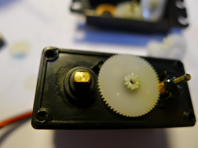
                                  The Gearbox Cover and Gears Removed

My servo had to be totally dismantled at this stage, you will also need to do this, so carefully remove the gearbox cover and take special note of how it all goes together, take a photograph so you get it right or it won't work. You will see why you need to do this a bit later. So, with mine apart I had to remove the pot and PCB together, you will see that the output shaft is connected to the position sensing potentiometer (Pot), the bigger brass looking shaft in the gearbox, you need to push this shaft out of the motor housing without breaking anything.

                                  The Pot shaft is on the Left, the big one


                                 Apply pressure to the Shaft to pop it out

Put the pot shaft against your bench, see image above, and firmly push it out of the motor housing, it is held in by a plastic clip so it will need a bit of pushing but be careful not to break anything.

                           The PCB and Pot came out Together in my Servo


                                     Unsolder the Pot Pins from the PCB

You need to cut the wires AT THE POT if yours is connected by wires or like mine you will need to unsolder the pins at the PCB, use a solder sucker and be careful not to unsolder the surface mounted components that are also connected to the pins, take you time and be very careful because they are hard to put back on, Clean out the holes so we can solder the two 2K7 Ohm Through Hole Resistors to the PCB or if your Pot had Wires you need to connect the resistors to the wires that you cut off at the pot.

                               Twist the Resistor Leads Together Like This


                                     Now Bent the Other Two Like This

Now twist two of the resistor leads together as in the first image above and then bend the other two as in the second image above. So if your servo had wires you will need to cut some heat shrink, three bits about 10mm long and slide them over the three cut wires, put the wire that went to the wiper onto the twisted pair of leads from the resistor and solder it, now slide the heat shrink up and heat it so it insulates the connection and leads, solder the other bent leads to the other two wires and solder them and insulate them with the heat shrink. It doesn't matter which way they go because we are making a voltage divider network and the wiper is the critical connection and goes to the middle of the voltage divider, that is the twisted pair of leads. In my servo it was a bit easier to do, see image below.

                                The Resistors Mount on the PCB as above


In my servo the resistors mount on the underside of the PCB and solder to the PCB, the important one is the twisted pair again and they must go where the wiper of the pot was, once again making a voltage divider network and the middle goes to the wiper connection. Take care not to damage the PCB and or the surface mount components on the PCB.


                          Mount a torch in your little vise or bench like this


              Now Inspect the PCB for Bridges or Damage as shown above


Mount a torch as in the first image above and position the finished PCB as in image two above  so you can see the light through the PCB and inspect it for solder bridges or damage, this makes it very easy to see any faults. no need to use heat shrink on this pair of resistors. Now put it all into the motor body making sure nothing can short out and in the same position as it was originally, look at the photographs to make sure it's all as it was.


                                    We Need to Modify the Output Shaft
We now need to modify the output shaft so it can rotate continuously, the stopper on the shaft that you can see on the right in the image above must be carefully removed. I use a very small hobby saw and cut it off at the top of the gear teeth, once removed I use a diamond file to make it flush with the teeth and flush with the shaft at the other end, be careful not to damage the teeth or the shaft and give it a good clean to remove the bits that you cut and file off.

Now put a bit of extra silicone lubricant on the gears and put the gears back together, look at the photograph to make sure they are as they should be and put a bit more silicone lubricant on the gears and output shaft, especially where the bush is for the output shaft itself.

                                  Gearbox Back Together and Lubricated


                          Note the extra Lubricant at the Output Shaft Itself


Now put both covers back on making sure that all gears and wiring are in their original positions and nothing gets caught up or damaged, put the screws back in and torque them so that you do diagonally opposites as you go. Once together you need to test them.


                                        The Test Setup on the Bench

Set up a test using an Arduino UNO or what ever you have and the Arduino IDE and the example sketches that come with the IDE, the servo should rotate one way continuously and then the other and not make strange noises and run freely both ways. The wiring for the servo is Red = 5V "+" and it is always the centre pin in the 3 pin plug, Black or Brown = 0V "-" and then Orange, White or Yellow = Signal from the Arduino or tester, now program the arduino with a sketch for servos and make sure the servo works as intended, remember the servos work on 5Volts and the arduino can power them but I recommend to power them from the battery or power supply directly, easier on the arduino regulator, just remember to join all 0Volt or earths together. Cheers, and have fun, Terry.