Saturday 14 March 2015

Motor Test, Tower Pro MG995

A while ago I purchased some Tower Pro MG995 All Metal Gears Servo Motors, I had used the plastic gear versions which were excellent so I was keen to test the metal gear version. I decided to make another autonomous robot but to keep it as simple and cheap as possible, the main reason was to test the motors only.
So I had been thinking of a simple design for a while now, based on a stink beetle but also a bit like a pentagon, so Stink Bot was born. In my usual style it's made from 3mm compressed particle board, or chipboard (MDF) and this time I experimented with some metal brackets that I got at Bunnings. I used an Arduino Pro Mini and based the sketch on the Tubby Bot because it works so well. I didn't use a switch this time, instead I used a two pin plug on the busbar to interrupt the earth or 0Volt line.


                                This is the shape I settled on, it was simple

                                  The final shape cut out of 3mm MDF

I decided to try the metal brackets so I cut them in half, marked the position of the holes and drilled as required, they are much stronger than the MDF ones I used last time and easier to make if the truth be known, for me that is.

                             Original on the left, modified middle and right

Once the holes were drilled I assembled the brackets on the motors and marked the holes for the chassis, I also marked each bracket to match the mounting position on the motors and motor position on chassis so all the holes would match up on final assembly, makes it much easier later on.

                                  Motors mounted on the painted chassis

                                I used one caster on the rear in the middle

I used a caster on the rear in the middle, it makes it so easy to steer the robot with the operation of motors, the layout I use is very stable as well, it will climb over small obstacles with ease, especially with the torque of these motors. It even moves very well over carpet.

                                              The look of the robot.

The motors mounted flush to the lower chassis which is what I wanted and I had to make provision for the wheels in the lower chassis and I like the look of the finished setup. As you will see later I had a huge amount of space to play with which opens up the robot for so many extras that could be mounted in it as well.

                        The ultrasonic sensor mounted on the upper chassis

I mounted the ultrasonic sensor on the top chassis and under cover to protect it from being hit if the bot runs into an obstacle, which it doesn't but you never know. The dowel size means that it goes either side of it as well so it worked out nicely for me. As always I recommend you mix and match your designs as well, give it some life.

                                        Look at the amount of room

The room is huge as I mentioned before so you could add so much to it. As I said I used the Arduino Pro Mini so it's very small, in fact it's held in via a cable tie or two only, the battery holder is held in place with hook and loop tape, dots actually made and sold by Velcro, yes it is called hook and loop tape, Velcro is a brand name. I know that some of you won't like the wheels coming through the chassis like this but I like it a lot so I will use this setup again. The metal brackets are so easy to modify.

                              The sensor mounted nicely behind the dowel


The sketch I used is a very simple one, it's the one that I used in the Tubby Bot and it works so well so I used it again. Have a look at Tubby Bot for the sketch.

            The busbar with the two pin plug on the right hand side, unplugged

I didn't want to use a switch, cost factor, so I set up a two pin and plug setup to isolate the power on the busbar as I mentioned, the busbar makes it very easy to supply the robot with power, it even makes it easy to have two different power supplies, one for the motor and one for the Arduino. Made up on protoboard (PCB) you can configure it in as many ways as you need, switching included. Once again I will point out the use of rechargeable batteries, 4 X 1.2Volts is 4.8Volts (5.27V fully charged) and 4 X 1.5Volts is 6Volts which is not at all good for the Arduino but great for the motors, hence setting up two power supplies to get the motors to go a bit faster and speed up the robot.

                                                           Stink Bot

He has turned out better than I thought, the motors were so easy to modify for continuous operation, large size helped so much and gave a large area inside the robot to hide the two voltage divider resistors that take the place of the trim pot. The metal gears were easy to remove the limit pin from the output shaft gear, good pliers and gentle twist and out it came, both times. The trim pots were held in by plastic clips that bent out of the way easily, didn't break so it can all be returned to normal operation later on if required, and yes I kept ALL the components that I removed so I can fix them later. Anyway, simple and quick build that I am very pleased with, especially the motors.


The build was great fun as always and I hope it inspires you to build a robot or two of your own, Cheers, TJ.


Monday 9 March 2015

Tubby Bot, Simple Autonomous Robot

Ya just gotta love these Rolling Robots, well my grandchildren love them. I had been looking for a simple but entertaining rolling robot for a while and I came across a little robot called PopPet by Jaidyn Edwards, a young Australian now producing professionally made versions of this lovable robot and selling them from his poppettherobot.com site and they are as cheap as chips in the kit form. This inspired me to have a go at designing something similar but I wanted to be able to make it from the bits that I had in my workshop now, I didn't want to buy a single thing. Mind you I will be purchasing one of the PopPet kits from Jaidyn. Now I supply this information as is, it is for entertainment purposes only and if you use it you do so at your own risk. That out of the way lets begin.

So what did I have in my workshop, 3mm compressed particle board, empty CD cases, all but empty tub of CD's, servo motors but the micro versions, an Arduino Pro Mini clone, an ultrasonic sensor, battery holder for 4 AA's and enough bits and pieces to put a simple robot together. I didn't want to follow my normal path and use the chipboard as the chassis so I decided to use the CD Tub that had only one CD in it. I wanted to make the wheels and caster from scratch and use as simple a sketch as I could to get it working and avoiding objects. I only had two servos so the ultrasonic sensor had to be fixed, that is it couldn't sit on a servo motor to move it around. Remember that some  Arduinos operate on 5Volts (Some operate on 3.3Volts) and 4, 1.5Volt AA's is 6Volts so ONLY USE RECHARGEABLE BATTERIES. 4, 1.2Volts is 4.8Volts. (Actually it's 5.27 fully charged in my setup but that's fine) Make sure that the Arduino you use is the 5Volt version otherwise change the power supply to match the board you use.
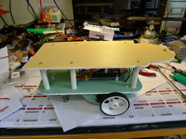
This is my version of the robot.

First the tub, I had to plan a layout that fitted all the components inside it and how to mount everything.

                                     The Tub that was to be the Chassis


                                 The two Tower Pro 9g Standard Servos

The small size of the servos meant I had a lot of room inside the tub and everything will fit inside it, even the battery holder with room to spare.

                                Small cutouts to let the motors mount flat

Once I knew where I was going to mount the servo motors I was able to measure the space available for the wheels and I cut the wheels out using a hole saw, the added advantage of that was it drilled the centre hole for the servo horn at the same time.


                                  The wheels and servo horns that I used


                                      The servo horns were self locating

The lucky part was the servo horns were self locating, but once you marked the holes and drilled them you have to turn the horns back over so the mounting head is pointing away from the hole, see my images.

                                        Holes marked and drilled


                         Take note of the mounting position of the servo horn


As you can see the servo horns are now mounted the other way up after you drill the holes, now you have to trim the excess screw thread down level to the nut, make sure it is tight after you trim it down. See my images below.


                                      Screws trimmed down to the nut

Okay wheels are done, you need to do one more thing so they can rotate without fouling things, the location pin next to the motor shaft needs to be trimmed off and filed flat, see the images below.

                       See the little location pin just to the left of the drive shaft


                                                Trim it off and file it flat

Next we need to modify the small servo motors for continuous rotation, that's a bit painful in little motors like these but it can be done. Two screws in the bottom of the motor, some might have four, remove them and take the bottom plate off the motor, I carefully pulled the electronic PCB up to gain access to the wiring that goes to the trim pot, I had to get a firm grip on the pot terminals, not the wiring, the metal tabs on the pot itself, a good wiggle and I pulled until the pot came out. Simples....

                        Motor end cap off and PCB up and out of the way


                      Trim pot out of the motor and wiring location recorded

As I said take note of how the pot is wired, especially the pot wiper connection and then cut the wires right at the terminals of the pot, leave all the wiring in place. Now get the two 1% 2K5 Ohm resistors and twist the end of both together and trim the excess wire, make it as short as is humanly possible yet secure and to be able to bend back on itself. Slip a length of heat shrink over the wiper wire and solder the wire to that twisted pair. That is the centre of the voltage divider network, it will be half the voltage supplied to the network. Slide the heat shrink up and over the solder joint and twisted wires so it is insulated. See the images below.

             Wires twisted together to form the centre tap of the voltage divider

              The other wires soldered to the other two ends of the resistors

             The three wires connected and ready to be protected in heat shrink

The other two wires are connected to the other two ends of the resistors, one on each and it doesn't really matter which wire goes to what as it is a voltage divider network made up of equal size resistors, now slide the heat shrink up and heat it so it shrinks and insulates the wires and resistors and put it all inside another bit of heat shrink but keep it as small as possible because it has to go inside the motor case and its a tight fit.
Now the gear box, you now need to remove the top of the motor to reveal the gearbox, take your time and take note of the layout as you go. Locate the gear that has the limit pin or block, see the photo below.

                                  The gear with the limit pin or block

The limit pin or block as above must be removed but be very careful not to damage the gear itself and now the metal shaft that locked into the trim pot, cut the section with the two flats off just below the flats so it no longer protrudes into the electronics section. Now put the motor back together, start at the gear box and work backwards, make sure everything is secure and can't cause short circuits and the like. replace the screws and your done. Lets get back to the tub.

                                  The tub base showing the wheel cutouts

You can now measure and mark out the holes for the wheels to extend through, see image above, take your time and measure twice and cut once and trial fit as you go and make fine adjustments as required. Remember that the wheels need to be aligned carefully for correct operation.

                                Motors on wheels ready for final assembly

As all of this was going on I took the top of the tub outside and roughed up the outer surface with fine sand paper and gave it a coat of paint, undercoat first and then the colours that I had chosen, really it was what paint I had to hand, lots of yellow and a bit of red. I had also measured up and drilled the holes for the ultrasonic sensor and on off switch so I didn't have to do it after I had painted it all and have the paint come off. Once again make a template for the sensor, makes it a lot easier.

                                       Motors mounted with Hot Glue

Okay, why hot glue you ask, because it's what I had, not only that if you sand the areas that the glue has to stick to it makes a far better bond and I have been using hot glue for many years and it has worked perfectly for me every time, get the preparation right and it will stick beautifully. How you mount it is up to you.


                    Note the Hot Glue applied to the cutouts from underneath

                                           My home made caster?

You can see in the image above that I made my own caster wheel, I am going to replace it, it works but not a well as I had hoped, it's on the bot in the video but I didn't show you the full video, I took the part where the bot over balances out, the caster swings around and in one spot it lets the bot over balance and loose traction, it just needs to be smaller, the centre of the pivot and centre of the wheel need to be closer together, I'm looking at making a ball caster for it.

                                  Wood wheels and caster in place

I did use wood glue on the caster wheel but I also used some hot glue to make it a bit more kid proof, the youngest grandson likes to pick it up and throw it, it did survive him, well 80% survive, the battery holder came away so I had to re-mount it but it was easily fixed and I made it stronger the second time around.
Back to the build, the wiring next.


                                       Busbar and motor connectors

The image above shows you the Busbar and Motor Connectors, making these means I can re-use the components and makes the hookup much easier and safer. The switch is wired in on the negative/0V line, I do it this way every time. Note the use of heat shrink over every soldered joint and also on the motor connectors to make it much more secure, develop good habits and your builds will last longer and have far less break downs. The Arduino Pro Mini has male pins so I was able to use the female terminals from Jaycar and some heat shrink tubing to insulate them. See image below.


                     Female Terminals used to connect to the Arduino Male pins

The top of the tub should be painted and dry, mount the ultrasonic sensor into the top and secure it with a bit of hot glue, at the same time solder the 0V/negative lead from the battery holder to the switch, don't forget the heat shrink, and mount the switch.


                                  Switch and ultrasonic sensor mounted

Make all the connection wires making sure that they are long enough to be able take the top off for servicing and changing batteries. I mounted the Arduino Pro Mini clone on the shaft on the base, it fitted over this shaft nicely with all the wires connected. I used a small amount of hot glue just to hold it while I put the cable tie around it for extra support, remember the grandson that sends it flying, it has to be strong. The wiring is made safe with a cable tie or two as well.

                   Arduino cable tied and excess motor wiring also cable tied


                         Busbar hot glued to the base and wiring made safe


                                   Battery holder mounted with hot glue

The components fitted inside the tub very well, remember to make the battery holder mount as strong as possible, I had to re-do mine, bit of extra sanding and extra layer of hot glue, strong as now. The connections to the Arduino will depend on the Sketch you use but now is a good time to test everything on the bench. WARNING, only use RECHARGABLE BATTERIES.


                                   All the wiring done and made safe


                           Final test fit of the top and some art work applied

We need to talk about the Sketch or Code that I used, I have been trying to learn the language of micro controllers for months and I have been collecting the code as I have been going. I stand on the shoulders of the many Great Women and Men that have gone before me and use this material that I collect and modify it for my projects. This is the beauty of Open Source and the community that supports it, just amazing so credit belongs to them not me, I simply change a few numbers around to make it all work in my project. That said, I can't remember where I got this code from and the author didn't put her/his name to it and I never remove the authors information, NEVER. It is Open Source and we are free to use it so here it is;

Simple_Servo_Obstacle_Avoidance _Robot_2015
#include <Servo.h>     //Inclue Servo Library
#include <NewPing.h>   //Include NewPing Library

Servo leftServo;       //Create Left Servo object
Servo rightServo;      //Create Right Servo object

#define TRIGGER_PIN  6   //Trigger pin of Ultrasonic sensor connected to pin 6
#define ECHO_PIN     7   //Echo pin of Ultrasonic sensor connected to pin 7
#define MAX_DISTANCE 100 //The maximum distance we want the sensor to look for is 1m

NewPing sonar(TRIGGER_PIN, ECHO_PIN, MAX_DISTANCE);  //Create Ultrasonic sensor object

unsigned int time;            //Variable to store how long it takes for the ultrasonic wave to come back
int distance;                 //Variable to store the distance calculated from the sensor
int triggerDistance = 30;     //The distance we want the robot to look for a new path
int fDistance;                //Variable to store the distance in front of the robot
int lDistance;                //Variable to store the distance on the left side of the robot
int rDistance;                //Variable to store the distance on the right side of the robot

void setup()
{
  leftServo.attach(9);        //Left servo connected to pin 9
  leftServo.write(90);        //Write the neutral position to that servo
  rightServo.attach(8);       //Right servo connected to pin 8
  rightServo.write(90);       //Write the neutral position to that servo
}

void loop()
{
  scan();                                //Get the distance retrieved
  fDistance = distance;                  //Set that distance to the front distance
  if(fDistance < triggerDistance){       //If there is something closer than 30cm in front of us
    moveBackward();                      //Move Backward for a second
    delay(1000);
    moveRight();                         //Turn Right for half a second
    delay(500);
    moveStop();                          //Stop
    scan();                              //Take a reading
    rDistance = distance;                //Store that to the distance on the right side
    moveLeft();
    delay(1000);                         //Turn left for a second
    moveStop();                          //Stop
    scan();                              //Take a reading
    lDistance = distance;                //Store that to the distance on the left side
    if(lDistance < rDistance){           //If the distance on the left is smaller than that of the right
      moveRight();                       //Move right for a second
      delay(1000);
      moveForward();                     //Then move forward
    }
    else{
      moveForward();                     //If the left side is larger than the right side move forward
    }
  }
  else{
    moveForward();                       //If there is nothing infront of the robot move forward
  }
}

void scan(){
  time = sonar.ping();                  //Send out a ping and store the time it took for it to come back in the time variable
  distance = time / US_ROUNDTRIP_CM;    //Convert that time into a distance
  if(distance == 0){                    //If no ping was received
    distance = 100;                     //Set the distance to max
  }
  delay(10);
}

void moveBackward(){
  rightServo.write(180);
  leftServo.write(0);
}

void moveForward(){
  rightServo.write(0);
  leftServo.write(180);
}

void moveRight(){
  rightServo.write(0);
  leftServo.write(0); 
}

void moveLeft(){
  rightServo.write(180);
  leftServo.write(180);
}

void moveStop(){
  rightServo.write(90);
  leftServo.write(95);
}


Remember if you use this sketch you may need to change some of it to work with your robot, It worked perfectly as is in mine. As I mentioned I not sure who the author is but my best guess is Jaidyn Edwards from poppettherobot.com as I think his work is amazing and I follow him on the Internet, his training videos are excellent.


                               This is a short video of Tubby Bot working

Well I hope you enjoyed this and you are now inspired to have a go at making your version of this little robot, my grandchildren have a ball with them and that alone makes it all worth while, remember I'm no expert at this and If I can do it so can you, all you have to do is have a go at it, enjoy. Cheers, TJ.


Sunday 8 March 2015

Simple Line Following Robot

So who doesn't love a robot, even in it's simplest form everyone loves a robot, in this case a rolling robot that follows a black line on a light or white background. I had already built a line follower using a TI MSP430G2231 and visible light and LDR's to sense the black line, I wanted to do one using an Arduino UNO and IR (Infrared) LED's and Photo Transistors. I searched the www and found just what I was looking for on DIY Hacking, a group of amazing people in India who believe in Open Source and share their knowledge freely on their site http://diyhacking.com and it is their 10 minute line following robot that I have based this build on but extended the build time to a few hours and made it a bit more permanent. Now I supply this information as is and if you use it you do so at your own risk.

                                The finished Line Following Rolling Robot

So the first step is to plan the robot, what power supply will you use, do you want to make the wheels, what about the Infrared Sensor, I made the sensor myself on Prototype PCB, okay you know how you will build it, you have your plan so lets do it.
I started with the woodwork, I drew the plan for the chassis on 0.3mm cardboard and cut them out and used them as templates for the build. The base was 120mm Wide, 200mm Long and 3mm Thick, the dowel was 10mm cut to 50mm lengths, 10 components to make up the chassis. Remember to make the top of the chassis an exciting shape but keep it similar in size to the lower board for balance. I glued the motor mounts to the bottom of the lower chassis board with the centre of the motor drive shaft 60mm from the leading edge of the lower chassis board and let it dry. I found the centre of each end of the dowel (top & bottom) and drilled holes so the self tapping screws wouldn't split the dowel. I drilled all the holes in the chassis for every component that will be mounted on the chassis, including the top chassis for the indicator LED, don't forget the hole for the Busbar, I talk about it later in the build.

                 The Lower Chassis with Motor Mounts glued on and held square

                          The Upper Chassis can be any shape but similar size

Now for the Infrared Sensor, you will need Six IR LED's and Six IR Photo transistors, Six 10K Ohm resistors, Two 220R Ohm Resistors, Prototype PCB, hook up wire and wire for the power, earth and sensor outputs. Have a look at the wiring diagram on DIY Hacking for the sensor, its easy but you need to plan the layout carefully. The LED's need to be 15mm apart with the photo transistors mounted behind them but very close for maximum output. I also used some heat shrink on the LED's to prevent stray infrared light getting into the photo transistors, check out my images below.

                      The IR Sensor Array, note the location of the components


                               You can see the Heat Shrink on the IR LED's

Lets look at the Busbar, it's made on the Prototype PCB and simply gives a number of pins for power, Positive and Earth or 0V, it all works on 5V for the sensor and Arduino BUT the motors works on 6V, I used two power supplies, a 9V battery for the Arduino and a 4 AA battery holder for the motor power supply. The Arduino supplied the 5V for the IR Sensor Array but remember to connect the earths together via the busbar, ONLY the earths. The battery box has a built in switch and the 9V battery has a 2.1mm plug and battery clip that I plug in and out as a switch.

                                The Busbar and Servo Motor Connectors

While your making the busbar you should make up the motor connector plugs as well, see above and below. The PCB male connector 0.1 pins can be cut to length or number of pins required and wires soldered to the short pin side and the longer side plugs into the motor connectors. Everything is protected by heat shrink tubing and held firm as well by the heat shrink.

                             Servo motor connectors, note the heat shrink

We are at the point where we need to grab the servo motors and modify them for continuous rotation unless you purchased them that way originally, I use the standard servos and do the mod, lots cheaper and works just as well and is a lot more fun doing the mod. You will need four 1% 2K5 Ohm resistors. I always remove the feedback trim pot and replace it with the two resistors wired in a voltage divider network with the centre tapped off to connect to the wiper wire, that way you get exactly half the voltage which is feedback for 90 degrees to the servo motor electronics. Now the gearbox needs to be modified, you need to remove the limit pin or plastic bit that prevents the gear from rotating fully, be careful not to damage the teeth on the gear and remove all the small bits of plastic so it doesn't get caught in the gears and if you have a bit of the grease used in the gearbox put a bit more on them. You can buy the grease if you want to but not totally required unless you wipe all of grease off. Google search if your not sure how to do the mod, 100's of sites out there show how to do it in many different ways.
I hope you have been keeping an eye on the glue, when it's dry paint the components of the chassis the colours that you have chosen, I always paint mine to protect the chipboard, water destroys it very quickly.

Time to get the sketch, it's available from DIY Hacking, open the Arduino IDE, compile the sketch and up load it to your Arduino. Now carefully connect all the electronics together on the bench and test the operation, carry out any modifications required to the sketch, it will need work to match your motors and IR sensor array. Take special note of the clearance that gives the best output to the Arduino from the IR Sensor Array, you will need this for final assembly. Once you are happy with the sketch and all is working as intended go and see if the paint is dry on the chassis, if it is clean out the holes of the excess paint and get it ready for the final assembly.

                      Testing the sketch on the bench and taking measurements

The final assembly, I made the wiring using female terminals that fit the male pins on the busbar and Arduino, I purchase the female terminals from Jaycar and I insulate them using heat shrink. I follow a wiring code of sorts, Red is always Positive, Black is Negative, Yellow is Signal wire to Servo Motors and so on, just makes it easy for me to trace faults later.

                                   Motors, Caster Wheel and IR Sensor

I mount the motors and caster wheel and then the IR sensor, adjusting it to the height that I measured earlier and put the wiring through the holes.

                                    Wiring connected and made safe

Sort the wiring out and tie it together with cable ties or tape and make it safe, don't want to let the smoke out just yet.

                                    Wheels on and rear caster adjusted

Once the wheels and caster are fitted I adjust the height of the rear caster to get the chassis level to the ground, looks better in my opinion. The wheels used are made for servo motors and I purchased mine from Wiltronics in Australia. The small caster I got at Bunnings as well as the 3mm compressed particle board.

                                    Dowel supports on the lower chassis

I had to swap the mounting of the sensor and front dowels over, I used the wrong holes for the sensor but it was easy, note the pre-drilled holes in the dowel, stops the self tappers splitting the dowel. I also put a small counter sink on the holes so the screws finish flush but it depends on the style of screw you use.

                               Top on and the LED is mounted at the front

I mounted the indicator LED to the top deck, it indicates what stage the sketch is in so you can wave the robot over the black line so it knows the maximum and minimum levels from the IR sensor.

                             The wiring to the indicator LED glued in place


                        Final position of the IR sensor and wiring made safe

Once the assembly was finished I made up a track on the white kitchen table, much to my wife's disgust and delight of the grandchildren and set it free, it worked beautifully, well it did on the second go, I had to make a final adjustment to the sketch to tidy up the servo motor operation, the left motor was creeping backwards very slowly so I had to adjust the stop or 90 degree position in the sketch to stop it but all worked well and I am very pleased with its operation, as are the grandkids.


Saturday just passed had the grandchildren at home with us and we played for ages with it on the kitchen table, little TJ wanted to make up different layouts so we went through a roll or two of tape even re-using it, anyway we had a fantastic time.