
So the first step is to plan the robot, what power supply will you use, do you want to make the wheels, what about the Infrared Sensor, I made the sensor myself on Prototype PCB, okay you know how you will build it, you have your plan so lets do it.
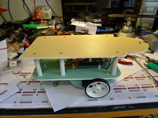
I started with the woodwork, I drew the plan for the chassis on 0.3mm cardboard and cut them out and used them as templates for the build. The base was 120mm Wide, 200mm Long and 3mm Thick, the dowel was 10mm cut to 50mm lengths, 10 components to make up the chassis. Remember to make the top of the chassis an exciting shape but keep it similar in size to the lower board for balance. I glued the motor mounts to the bottom of the lower chassis board with the centre of the motor drive shaft 60mm from the leading edge of the lower chassis board and let it dry. I found the centre of each end of the dowel (top & bottom) and drilled holes so the self tapping screws wouldn't split the dowel. I drilled all the holes in the chassis for every component that will be mounted on the chassis, including the top chassis for the indicator LED, don't forget the hole for the Busbar, I talk about it later in the build.


Now for the Infrared Sensor, you will need Six IR LED's and Six IR Photo transistors, Six 10K Ohm resistors, Two 220R Ohm Resistors, Prototype PCB, hook up wire and wire for the power, earth and sensor outputs. Have a look at the wiring diagram on DIY Hacking for the sensor, its easy but you need to plan the layout carefully. The LED's need to be 15mm apart with the photo transistors mounted behind them but very close for maximum output. I also used some heat shrink on the LED's to prevent stray infrared light getting into the photo transistors, check out my images below.


Lets look at the Busbar, it's made on the Prototype PCB and simply gives a number of pins for power, Positive and Earth or 0V, it all works on 5V for the sensor and Arduino BUT the motors works on 6V, I used two power supplies, a 9V battery for the Arduino and a 4 AA battery holder for the motor power supply. The Arduino supplied the 5V for the IR Sensor Array but remember to connect the earths together via the busbar, ONLY the earths. The battery box has a built in switch and the 9V battery has a 2.1mm plug and battery clip that I plug in and out as a switch.

While your making the busbar you should make up the motor connector plugs as well, see above and below. The PCB male connector 0.1 pins can be cut to length or number of pins required and wires soldered to the short pin side and the longer side plugs into the motor connectors. Everything is protected by heat shrink tubing and held firm as well by the heat shrink.

We are at the point where we need to grab the servo motors and modify them for continuous rotation unless you purchased them that way originally, I use the standard servos and do the mod, lots cheaper and works just as well and is a lot more fun doing the mod. You will need four 1% 2K5 Ohm resistors. I always remove the feedback trim pot and replace it with the two resistors wired in a voltage divider network with the centre tapped off to connect to the wiper wire, that way you get exactly half the voltage which is feedback for 90 degrees to the servo motor electronics. Now the gearbox needs to be modified, you need to remove the limit pin or plastic bit that prevents the gear from rotating fully, be careful not to damage the teeth on the gear and remove all the small bits of plastic so it doesn't get caught in the gears and if you have a bit of the grease used in the gearbox put a bit more on them. You can buy the grease if you want to but not totally required unless you wipe all of grease off. Google search if your not sure how to do the mod, 100's of sites out there show how to do it in many different ways.
I hope you have been keeping an eye on the glue, when it's dry paint the components of the chassis the colours that you have chosen, I always paint mine to protect the chipboard, water destroys it very quickly.
Time to get the sketch, it's available from DIY Hacking, open the Arduino IDE, compile the sketch and up load it to your Arduino. Now carefully connect all the electronics together on the bench and test the operation, carry out any modifications required to the sketch, it will need work to match your motors and IR sensor array. Take special note of the clearance that gives the best output to the Arduino from the IR Sensor Array, you will need this for final assembly. Once you are happy with the sketch and all is working as intended go and see if the paint is dry on the chassis, if it is clean out the holes of the excess paint and get it ready for the final assembly.

The final assembly, I made the wiring using female terminals that fit the male pins on the busbar and Arduino, I purchase the female terminals from Jaycar and I insulate them using heat shrink. I follow a wiring code of sorts, Red is always Positive, Black is Negative, Yellow is Signal wire to Servo Motors and so on, just makes it easy for me to trace faults later.

I mount the motors and caster wheel and then the IR sensor, adjusting it to the height that I measured earlier and put the wiring through the holes.

Sort the wiring out and tie it together with cable ties or tape and make it safe, don't want to let the smoke out just yet.

Once the wheels and caster are fitted I adjust the height of the rear caster to get the chassis level to the ground, looks better in my opinion. The wheels used are made for servo motors and I purchased mine from Wiltronics in Australia. The small caster I got at Bunnings as well as the 3mm compressed particle board.

I had to swap the mounting of the sensor and front dowels over, I used the wrong holes for the sensor but it was easy, note the pre-drilled holes in the dowel, stops the self tappers splitting the dowel. I also put a small counter sink on the holes so the screws finish flush but it depends on the style of screw you use.
I mounted the indicator LED to the top deck, it indicates what stage the sketch is in so you can wave the robot over the black line so it knows the maximum and minimum levels from the IR sensor.


Once the assembly was finished I made up a track on the white kitchen table, much to my wife's disgust and delight of the grandchildren and set it free, it worked beautifully, well it did on the second go, I had to make a final adjustment to the sketch to tidy up the servo motor operation, the left motor was creeping backwards very slowly so I had to adjust the stop or 90 degree position in the sketch to stop it but all worked well and I am very pleased with its operation, as are the grandkids.
Saturday just passed had the grandchildren at home with us and we played for ages with it on the kitchen table, little TJ wanted to make up different layouts so we went through a roll or two of tape even re-using it, anyway we had a fantastic time.
No comments:
Post a Comment